MH17: как и кто?

Информация о пользователе

Привет, Гость! Войдите или зарегистрируйтесь.


Вы здесь » MH17: как и кто? » Отчеты и доклады DSB и JIT » Отчет DSB 13.10.15: MH17 Crash Appendix Y - TNO Report


Отчет DSB 13.10.15: MH17 Crash Appendix Y - TNO Report

Сообщений 31 страница 42 из 42

31

Appendix A | 5 / 9

A.1.3 Design II, terminal velocity 730 m/s
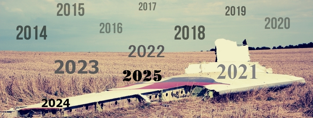
The simulation result is shown in Figure A.4. The most favourable warhead position
and orientation fulfils the match conditions.

https://d.radikal.ru/d14/1907/dd/864b6dcc8202.png

Figure A.4: Impact pattern (above) and corresponding fragment trajectories (below) of warhead design II,
velocity 730 m/s, position [0.0 m, -2.0 m, 3.7 m], orientation [-27°, 10°] and number of hits 1186

32

Appendix A | 6 / 9

A.1.4 Design III, terminal velocity ~600 m/s
The simulation result is shown in Figure A.5. The most favourable warhead position
and orientation fulfils the match conditions.

https://c.radikal.ru/c34/1907/eb/4a9eef49ae55.png

Figure A.5: Impact pattern (above) and corresponding fragment trajectories (below) of warhead design III,
velocity ~600 m/s, position [0.5 m, -2.3 m, 3.4 m], orientation [-27°, 10°] and number of hits 1216.

33

Appendix A | 7 / 9

A.1.5 Design III, terminal velocity 730 m/s
The simulation result is shown in Figure A.6. The most favourable warhead position
and orientation fulfils the match conditions. Figure A.7 shows an alternative
warhead position and orientation, mentioned in a study by Almaz Antey [8]. This
case fulfils the set matching condition in a very limited fashion.

https://a.radikal.ru/a03/1907/49/afb26e9f7544.png

Figure A.6: Impact pattern (above) and corresponding fragment trajectories (below) of warhead design III,
velocity 730 m/s, position [0.5 m, -2.3 m, 3.4 m], orientation [-24°, 7°] and number of hits 1254.

34

Appendix A | 8 / 9

https://c.radikal.ru/c23/1907/e4/13565378443b.png

Figure A.7: Impact pattern (above) and corresponding fragment trajectories (below) of warhead design III,
velocity 730 m/s, position [1.4 m, -0.8 m, 3.0 m], orientation [-72°, 22°] and number of hits 898 (of
which 810 are in the cockpit area)

35

Appendix A | 9 / 9

A.2 Summary
The results are summarised in Table A.1. The best match with the observed
damage on the airplane is found with design II and a SAM terminal velocity of
730 m/s. The poorest match is found with design III, a SAM terminal velocity of
730 m/s and the stated warhead orientation according to Almaz Antey [8].

Table A.1: Result of the damage matching procedure. Warhead position (X, Y, Z) and orientation
(azimuth, elevation) in the reference coordinate system.
https://a.radikal.ru/a25/1907/78/7107b8bcdb79.png

The results show that:
• It is possible to match different positions and orientations for different
warhead designs; finding a single combination for the point of detonation
and orientation is not possible.
• The found detonation points are inside a limited solution space. The
warhead position changes only by a little across the different simulation
cases. The results are sensitive for the warhead orientation. This is due to
the close proximity of the point of detonation.

36

Appendix B | 1 / 7

B Impact pattern of a 40 kg warhead
During the investigation into the cause of the crash of Malaysia Airlines flight MH17
the possibility of a lighter warhead (lighter than 70 kg) was discussed. The
hypothesis is that a match with the observed damage is found when a lighter
warhead would detonate closer to the airplane. The DSB asked TNO to investigate
this possibility.
This appendix contains the results of the damage matching procedure for three
designs of a 40 kg warhead with preformed fragments.
B.1 Engagement scenario
For a meaningful simulation it is necessary to establish an engagement scenario.
The airplane and the warhead have approached each other according to certain
flight trajectories. Of importance for the terminal ballistics simulation is only the
situation shortly before the detonation event.
The airplane is located in the simulation at Flight Level 330 and flies with 254 m/s
ground speed. The warhead is carried by a guided weapon. The type of guided
weapon is yet unknown, so in this case two terminal velocities have been taken for
the guided weapon, which are relatively far apart: 500 m/s and 800 m/s.
In consultation with the DSB, starting point for the simulation has been taken to be
the situation where the warhead detonates within 1.5 m from the airplane to cause
the observed damage. This corresponds in the reference coordinate system with
position [0.8 m, -1.6 m, 2.0 m].
B.2 Warhead designs
Starting point for the damage matching process is a warhead of about 40 kg with
about 4000 preformed fragments. With these data, TNO made three warhead
designs, which differ mainly in the range of possible fragment ejection angles (see
Table B.1).
Table B.1: Performances of three 40 kg warhead designs.

Property

Design A
(cylindrical)

Design B
(barrel shaped)

Design C
(tapered)

Number of preformed
fragments

~4000 (square,
~3 grams each)

~4000 (square,
~3 grams each)

~4000 (square,
~3 grams each)

Minimal ejection angle [°]

79

68

50

Maximal ejection angle [°]

100

111

115

Minimal velocity [m/s]

~1600

~1800

~1800

Maximal velocity [m/s]

~2000

~2000

~2100

Detonation position

Middle

Middle

Middle

37

Appendix B | 2 / 7

https://a.radikal.ru/a22/1908/2a/076441bbfc74.png

Figure B.1: Cross-sectional views of three warhead design by which it is physically possible to eject the fragment mass with
the angles and velocities specified in Table B.1. From left to right: cylindrical (design A), barrel shaped (design B)
and tapered (design C). The red dots mark the starting point of the detonation by which the explosive charge
(yellow) ejects the fragment on the casing (blue).

B.3 Simulated fragment hit pattern
The geometric centres of the three warhead designs are put on the specified
detonation position and simulated for the two terminal velocities. The orientation of
the warhead is varied to obtain a damage resembling the actual damage.

38

Appendix B | 3 / 7

B.3.1 Design A, terminal velocity 500 m/s
The simulation result is shown in Figure B.1. The corresponding warhead
orientation in the reference coordinate system is -35° azimuth en 0° elevation.
The match conditions are not fulfilled under the most favourable orientation.

https://b.radikal.ru/b01/1908/0a/894cb2f3fa85.png

Figure B.1: Fragment impact pattern (above) and corresponding fragment trajectories (below) of warhead
design A, velocity 500 m/s, position [0.8 m, -1.6 m, 2.0 m], orientation [-35°, 0°] and number of hits
961.

39

Appendix B | 4 / 7

B.3.2 Design B, terminal velocity 500 m/s
The simulation result is shown in Figure B.2. The corresponding warhead
orientation in the reference coordinate system is -40° azimuth en 5° elevation.
The match conditions are not fulfilled under the most favourable orientation.

https://a.radikal.ru/a43/1908/22/f30b34a2a63b.png

Figure B.2: Fragment impact pattern (above) and corresponding fragment trajectories (below) of warhead
design B, velocity 500 m/s, position [0.8 m, -1.6 m, 2.0 m], orientation [-40°, 5°] and number of hits
897.

40

Appendix B | 5 / 7

B.3.3 Design C, terminal velocity 500 m/s
The simulation result is shown in Figure B.3. The corresponding warhead
orientation in the reference coordinate system is -35° azimuth en 5° elevation.
The match conditions are partly fulfilled under the most favourable orientation

https://d.radikal.ru/d16/1908/32/cceec34612b9.png

Figure B.3: Fragment impact pattern (above) and corresponding fragment trajectories (below) of warhead
design C, velocity 500 m/s, position [0.8 m, -1.6 m, 2.0 m], orientation [-35°, 5°] and number of hits
888.

41

Appendix B | 6 / 7

B.3.4 Design A, two terminal velocities
The best match for warhead design A with SAM terminal velocity 500 m/s (see
Figure B.1) is compared with the best match for 800 m/s in Figure B.4. The match
for the higher terminal velocity is less fitting because the damage area decreases.

https://a.radikal.ru/a23/1908/c8/152cb2223dc4.png

Figure B.4: Fragment damage pattern of warhead design A, position [0.8 m, -1.6 m, 2.0 m]. On left: velocity
500 m/s, orientation [-35°, 0°]. On right: velocity 800 m/s, orientation [-25°, 0°].
B.3.5 Design B, two terminal velocities
The best match for warhead design B with SAM terminal velocity 500 m/s (see
Figure B.2) is compared with the best match for 800 m/s in Figure B.5. The match
for the higher terminal velocity is less fitting because the damage area decreases.

https://b.radikal.ru/b30/1908/d8/a2b3e4f304cc.png

Figure B.5: Fragment impact pattern of warhead design B, position [0.8 m, -1.6 m, 2.0 m]. On left: velocity
500 m/s, orientation [-40°, 5°]. On right: velocity 800 m/s, orientation [-25°, 0°].
B.3.6 Design C, two terminal velocities
The best match for warhead design C with SAM terminal velocity 500 m/s (see
Figure B.3) is compared with the best match for 800 m/s in Figure B.6. The match
for the higher terminal velocity is less fitting because the damage area decreases.

42

Appendix B | 7 / 7

https://d.radikal.ru/d01/1908/2f/a2ae1897a2e4.png

Figure B.6: Fragment damage pattern of warhead design C, position [0.8 m, -1.6 m, 2.0 m]. On left: velocity
500 m/s, orientation [-35°, 5°]. On right: velocity 800 m/s, orientation [-30°, 5°].
B.4 Analysis and summary
A partial match with the observed damage on the airplane is found with design C
and a terminal velocity of the guided weapon of 500 m/s. The other warhead
designs do not match because of non-compliancy with the damage conditions (see
Section 5.2).
Design C is extreme, in the sense that the angular range of the fragment ejection is
made as large as physically possible. Only with an extreme angular range it proves
possible to remotely approximate the observed damage pattern.
Increasing the terminal velocity to 800 m/s results in a general deterioration of the
matching result. The higher terminal velocity decreases the damage area in the
X-direction and increases the fragment density in that area.
The damage pattern of a lighter warhead closer to the airplane does not resemble
the damage pattern of a heavier warhead further away from the airplane.
Therefore, TNO judges the hypothesis that a lighter warhead can cause the
observed damage as being improbable.


Вы здесь » MH17: как и кто? » Отчеты и доклады DSB и JIT » Отчет DSB 13.10.15: MH17 Crash Appendix Y - TNO Report